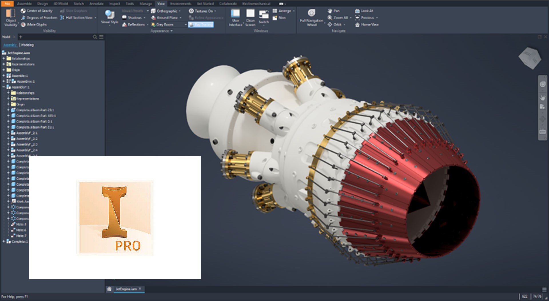
What Is Tube and Pipe Feature in Autodesk Inventor?
buy autodesk inventor 2023 has a tool or feature of tube and pipe. Tube and pipe have a sub-feature of 3d sketch conversion to tube and pipe of various styles, sizes (JIS, DIN, ASME, ISO… etc), material properties and other related properties of each spec in an editable manner. Although one can model 3d piping of each standard in any 3d cad software manually, for that one needs all necessary information related to each style dimensions and other properties of fittings, pipes, elbow, tee and other related parts of piping. buy autodesk inventor 2023 has solved this problem using tube and pipe feature, providing ease of 3d modeling, greater flexibility, related piping style and other engineering information.
Why Industries Need this Feature?
- Different types of industries and their needs
There are several types of industries producing a different type of products across the globe. Each industry has its own specific needs of piping depending upon product, safety, environmental concern and many other engineering and non-engineering contributing factors. This tool is very useful in the design of process equipment, tube bundle for various types of heat exchangers, machine piping, automobile piping and many other applications. For instance; airplane piping standard is far away from piping used in automobiles.
- Different engineering approach and style
Another important thing is; own style of engineering and thinking of each country. Sometimes on a same industrial process, the different piping standard can be applied successfully. Sometimes institutes of one country developed their own standards to facilitate their needs and ease of fabrication.
Necessary Things; while Creating Sketch
To create a 3d sketch for 3d piping, following conditions should be satisfied. Lines should be tangents or at the right angle. The proper constraint should be applied at all sections of 3d lines in drawing in inventor part(ipt). Length of each line segment should be selected according to rule and fitting dimension of each standard style and its related sizes. Fittings should find proper bend radius, reasonable length should be available at corners.
How to Draw a Sketch for Piping
Sketch can be drawn in two ways.
- Separate inventor part(.ipt)
Open new part in inventor(ipt). Go to 3d sketch tab, select line, draw line according to your requirement only in x, y or z-direction at the right angle. Line segment length should be chosen according to your pipe size, standard style, and process design. You should apply constraints manually or automatically, activate automatic tab and recheck again after drawing. Click the finish sketch tab. Save the file and open new assembly part in inventor and insert as a part (.ipt) file in assembly and proceed according to the given procedure. Creating a part in an assembly(.iam)
- Open new assembly file in inventor.
Create new part(ipt) in assembly(iam) file.Draw sketch as mentioned above, finish the sketch, save the file and return to assembly mode. Now you can proceed for piping.